Joysticks 101. Basically, we’ve got two types of joysticks: analog and digital. You’ve probably used both kinds. The buttons work pretty much the same on either kind – you either click it or you don’t – but the actual “stick” part is what makes them different. This post starts out with some basic joystick info and then some info about how you can use a joystick with a microcontroller.
Analog vs Digital
You know what digital means right? You’ve seen Tron, yes? When we say digital, we’re talking about 1’s and 0’s, on and off, yes and no, true and false, high and low. Digital “things” only know two states. CD’s? Yeah, they’re digital. All the music on that disc is described through 1’s and 0’s. No 1/28th’s and no .8273’s. It’s true.
Analog is a whole other thing. Records and tapes? Those are analog. The music on those are described by a whole range of values – the record has rolling hills and valleys that the needle follows and the tape has a whole range of magnetic signals, from strong to weak. Music is just one analogy. There are digital and analog versions of things all around us.
So, back to joysticks. Nintendo, Atari, and standup arcade games have digital joysticks. What that means is, no matter how far or short you push the stick to the left, you gotta face it – Mario’s either running left or he’s not. You remember when your boy was sitting on the rug next to you during his turn and he was all leaning over bumping into you because his body thought that he was somehow making Pitfall Harry run faster before hitting that edge? Seriously dude, he’s either running or he’s standing still. All or nothing. One or zero.
Analog joysticks work differently. PC joysticks and the old school home-computer joysticks (for an Apple II maybe) are analog. If you push the joystick a tiny bit to the right, you really do get a different result than if you push it all the way. Instead of just “right” and “no-right”, you have a whole range of positions between standing still and running. You might remember analog joysticks because they usually have “trim levers” on them. Basically they allowed you to calibrate the joystick so your guy wasn’t moving a tiny bit when the joystick was just sitting on the table. That’s kind of like the hissing you hear in the background of an audio tape when there’s supposed to be NO sound playing. Hey, it’s not digital.
Analog PC Joysticks
Okay, enough baby talk. No segway. Now we’re talking about microcontrollers, physical computing, and art. You have some brilliant idea for a computer-controlled sculptural installation that makes a powerful sociopolitical statement – and for whatever reason, you want the user to interact with the piece via a joystick. Okay. You’ll have to use my description above to decide whether you should be using an analog or digital joystick, but let’s assume you’ve decided on an analog PC joystick. Here’s the deal:
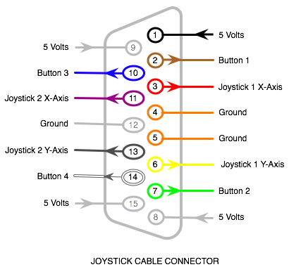
The connector that you’ll find on the end of that joystick will have 15 pins with the meanings shown in the diagram below. There’s actually a good chance that the colors of the wires will match what I’ve shown here (but to make sure you might have to peek inside the cable or joystick and check the continuity between each wire and each pin). In the diagram, the arrows show the direction that the signals are traveling – an arrow toward the pin means that the signal is going from the PC (or your microcontroller) to the joystick.
Another thing to note in that diagram is that some of the pins’ functions are duplicated. That’s because a PC game port (where the joystick would plug into) can use those 15 pins to control two joysticks – each with their own set of two “fire” buttons and each with their own stick. But we’re in America and we North Americans are greedy and fat. So, in practice, the PC joystick you buy at Saver’s will probably have two sticks on it, and four “fire” buttons, and maybe two “turbo” buttons (which just press the other buttons really fast in succession using something like a 555 timer). Basically, it’s pretending to be two joysticks and most games are okay with this fakery. For example, your flight simulator can use one stick for flaps and one for rudder (or whatever they do, I don’t know anything about planes) in the same joystick. If you really are using two separate joysticks, the pins on the left side of the diagram are for one joystick and the right side is for the other joystick.
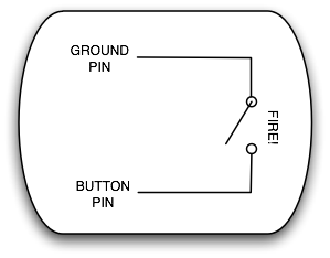
So, the “fire” buttons are really easy to wire up to your microcontroller. They work just as you’d expect from anything digital – they’re either on or off. You connect those wires to your microcontroller’s digital inputs and that’s that.
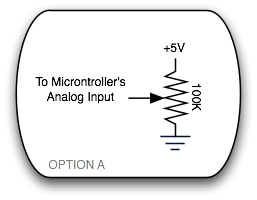
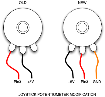
The stick part, however, is more interesting. The stick uses two potentiometers – one for the X-direction and one for the Y. You might be used to connecting potentiometers to your microcontroller using all three of its legs – like Option A below – but that’s not how the potentiometer is wired inside the joystick.
Actually, each of the two pots is wired like the “OLD” version in the figure below. One option you have for connecting this thing up to your microcontroller is to change the wiring inside the joystick to look like the “NEW” half of the figure. It’ll be easy on most joysticks and annoying on others.
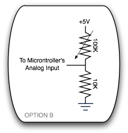
There is another way, so don’t go busting up your joystick if it doesn’t look like it wants to be subjected to that kind of tampering. The other way of wiring any pot to your microcontroller is show here in Option B. This works with the two-leg wiring of the pot inside the joystick, so you could go with this. The joystick pots are supposed to be 100kΩ so the 10kΩ resistor going to ground is an okay value.
Accuracy?
One thing to note is that the potentiometers in all of the PC joysticks that I played around seemed to have a strange range to them. For example, the pots in one they call the “Raptor” show very little change in the resistance when you’re way out to the right or left (or up or down). In other words, having the joystick 80% to the right was the same as having it 100% to the right. Apparently, joystick pots are designed to have less of a turning range than a normal pot that you might have lying around. This may make sense for most joystick designs since you can only move the joystick a relatively short distance from full-left to full-right. I suspect the Raptor’s huge sweeping range wasn’t taken into account when they decided on such a limited potentiometer.
Another interesting example is the lop-sidedness of wheel on the “Ultra Racer PC” joystick. Check out the video and notice how little effect the right direction has as compared to the left. Maybe it’s supposed to work like this for the game that it’s designed for – you do make all left-hand turns in a car racing game, don’t you? On both of these joysticks, the trim levers did help a bit but didn’t “fix” them.
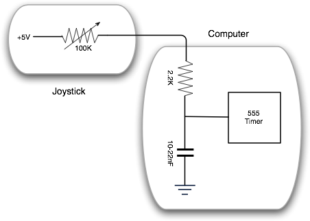
Anyway, a third option that you have is to use the joystick wiring as it was actually intended. This is a lot more complicated but it’s pretty interesting and I guess you might want to do it if you were short on analog pins on your microcontroller or something. Basically, what you’re doing is changing analog to digital. Something similar happens inside your microcontroller when you connect a pot to an analog input pin, saving you from the hassle of doing something like this, but it’s interesting to see how it happens inside a PC’s game port and it wouldn’t be terribly hard to do something like this with your project.
What’s happening here is that the joystick is letting the capacitor inside the game port get energized at a specific rate. That rate depends on how far you’ve pushed the stick. When the capacitor is fully charged, the output on the 555 timer (or similar) is high (+5V). Meanwhile, the 555 timer is triggered from the PC side every so often. When that happens, it grounds the capacitor – “emptying it out”, the output of the timer goes low (0V), and the capacitor starts filling up again. At some point, the cap is fully charged again and we’re back to the beginning. So, basically, the time between when the timer’s output goes low (the cap is emptied) and when it goes high (the cap is full) tells us everything we need to know about the position of the stick. I said the position of the stick is directly related to how fast the capacitor fills up, right?
In a real game port there are four of these – one for each axis (X & Y) of each joystick. So it’s probably not a 555 timer – it’s probably a chip with four timers rolled into one. But otherwise, it’s the same thing that I described. You could do this. You could do it without a timer at all, probably. I mean, your microcontroller can do everything a 555 timer (or four of them) could do standing on its head, right? But, in the end, the only good reason to do all this is if you don’t have the ADC pins available.
Digital Joysticks
Most digital joysticks are easier to interface with, depending on where they come from. If it’s an Atari joystick or one of the many joysticks that came after it (for the C-64 and other home computers), it should be real easy. There’s one ground pin that each of the switches is connected to. If the connection between that ground pin and the pin for a given button is closed (ie: they’re connected), then that button is pressed. Simple, yes?
You can find the pinouts for the Atari joystick and all the variations from the links below, but once you’ve found the ground pin it shoudn’t be hard to map out the rest. Draw it in your sketchbook.
Paddles
Atari paddle joysticks and some others actually use one of the unused pins for +5V power and two of the other pins for potentiometers. Analog! Sneaky bastards. Whatever, you know the analog story by now. The pots in an Atari paddle are 1MΩ, by the way.On the more difficult end of things, there are the Nintendo and Super Nintendo joysticks. Basically, these joysticks communicate with the game system (or your system) using a serial protocol. It’s actually not that hard to understand, but you can’t expect a specific pin to be associated with a specific button like an Atari joystick. It don’t work that way. I’m about to post an Arduino library that will handle the communication for you, so I’ll stop here. The NES and SNES joysticks are kind of an anomaly and most of the crap digital joysticks that you’d see at a thrift store or yard sale will be of the Atari one-pin-per-function variety. All you need to do with one of those types of sticks is use the continuity setting on your multimeter to figure out the layout of the pins or find a diagram of the pinout on one of the web sites below.
Links
- epanorama.net joystick pinouts and projects
- pinouts.ru video game pinouts
- Tons of information from Tomi Engdahl
- Craig Lisowski’s Atari info (in the Mirrors section at the bottom)
- Pack Man uses 5 joysticks with one microcontroller by polling them each in turn
- The arduino joystick tutorial works for a joystick that has been modified from “OLD” to “NEW” (see above)
